Power Conversions: Chargers Are Power Converters
Part of Chapter Utility Battery Chargers
Video
WHY DC POWER?
2.1.1
Modern institutions rely increasingly on electrical and electronic controls. Where continuous service is critical, redundant power sources are needed to ensure reliability. Where locally-provided redundant power is required, the use of dc powered controls, operating on storage batteries, is one of the most reliable solutions. In stationary applications, ac power from the mains is converted directly to dc to provide power to controls and operating equipment, while maintaining a battery to provide emergency power. In motive power applications, the dc power is used only to restore the charge to the battery, which is used elsewhere.
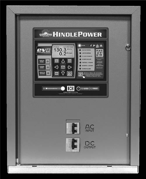
Most of the battery-powered installations in the US are based on lead-acid batteries. While the conversion of ac power to dc power is independent of the storage medium, the major focus of this section will be on chargers for lead-acid batteries, such as the one pictured in Figure 2a.
RECTIFICATION: HOW DO WE CHANGE AC TO DC?
2.1.2
In the beginning, there was the dynamo. Actually, there wasn’t even a dynamo. Although Planté invented a practical storage battery in 1859, early experimenters had no way to charge it other than using primary batteries. Doing that today, we would quickly consume the world supply of zinc.
Anyway, back to the dynamo. Siemens and Wheatstone each developed practical dc generators, or dynamos, by 1867. This led to the first practical way to charge the infant lead-acid battery. When Camille Alphonse Faure invented the pasted-plate lead-acid battery in 1881, we finally had an easily manufactured source of stored dc power, and the battery could be easily recharged using a dynamo (usually steam powered). However, there was no ac power yet. No grid or mains. No substations. No transformers. These words weren’t even in the English language yet. Also, no power failures.
But I digress. You want to know about changing ac power to dc power. Tom Edison was distributing dc power in limited areas in the late 1800s. You know how that turned out. By the mid-1890s, Westinghouse had won the “current wars,” and was building widespread ac distribution systems. Now that customers had a source of ac power, they needed a means to convert it to dc to charge their storage batteries. That was the dynamo, mechanically coupled to an ac motor (the M-G set, which puts the ac motor part and the dc generator part in the same machine, came later).
Dynamos*, of course, have some disadvantages, chief among them being weight, floor space, and maintenance requirements. By the 1920s, vacuum-tube or gas-filled rectifiers (ignitron, thyratron) were replacing dynamos in static converters (that is, no moving parts). Finally, by the 1960s, silicon diodes and SCRs (silicon controlled rectifiers), used in various circuit configurations, came to dominance in converter technology. The rectifier circuit, of course, is at the heart of any battery charger. Although chargers are frequently called “rectifiers” in stationary applications, we’ll use the term “rectifier” here to mean only the part of a battery charger that changes ac to dc.
POWER SUPPLIES: HOW RELATED TO BATTERY CHARGERS?
2.1.3
A battery charger, as you will see, is a special case of a dc power supply. Common technologies used in power supplies are discussed here.
Linear Power Supplies
2.1.3.1
Linear power supplies usually consist of a transformer, rectifier circuit, output filter, and control circuit. Since the rectifier operates at line frequency (60 Hz in the Americas), extensive filtering is required. They are capable of very accurate dc voltage control and are suitable for low power applications; they’re frequently used for variable output voltages, such as laboratory power supplies. Their efficiency is limited unless designed for a specific constant load.
Ferroresonant & Magnetic Amplifier Designs
2.1.3.2
For high power applications (up to 100 kW or more), power supplies using magnetic controls have been developed. Ferroresonant supplies (aka “ferros”) depend on the characteristics of a special transformer design, whose secondary voltage is fiercely independent of changes in the input voltage; that is, it’s an excellent line regulator. The transformer has inherent current limiting, which by design could be as low as 200% of the power supply rated output. The rectifier circuit uses only silicon diodes, so the supply is extremely rugged. Efficiency is good at full load, and input power factor is high. A variant, the controlled ferroresonant transformer, improves the output voltage regulation at the expense of added complexity, and provides the capability to have separate float and equalize voltages. But, the transformer is larger than a standard linear transformer, generates more acoustic noise, and costs more. It operates only on single-phase ac sources; a three-phase power supply requires two or three transformers.
A magnetic amplifier (usually called “mag amp”) power supply also uses a special transformer design, or a standard transformer coupled with another magnetic component, a saturable reactor. Like the ferroresonant supply, it uses silicon diodes in the rectifier, and is extremely rugged, although it lacks the high input power-factor of the ferro. The mag amp supply is available in single-phase or three-phase versions. One limitation of the mag amp rectifier is that the dc output current cannot be reduced to zero, so loading or bleed resistors are required for effective float-voltage control.
Phase Control Power Supplies
2.1.3.3
We’ve previously mentioned ignitrons, thyratrons, and SCRs. These are all examples of controlled rectifiers – that is, they are electronic devices that, like diodes, conduct current in only one direction. Unlike diodes, which have only two terminals (an input and an output), they have (at least) a third control terminal. They will conduct, or “turn on,” only when given a signal to do so at the control terminal. This gives rise to phase-con-trolled rectifiers: the rectifier element (SCRs in modern supplies) conducts for only part of each cycle of the ac input power. By adjusting the conduction duration in each cycle, the power supply can control its output current from zero to its maximum rating.
The combination of a linear transformer and silicon controlled rectifiers makes for a very rugged supply. Phase control supplies can have very high efficiency, even at light loads, and have lower costs than mag amp or ferro supplies of the same rating. Because the output voltage waveform is discontinuous, however, the dc output requires more filtering, and there are more harmonics in the input current than for a ferro. But three- phase versions are simple and reliable, and don’t suffer from potential instabilities that may occur in magnetically controlled supplies.
An exhaustive explanation of how phase control works appears in CHAPTER 3, Ripple & Filtering.
Switching-Mode Power Supplies (SMPS)
2.1.3.4
All the power supply designs that we’ve discussed use transformers to isolate the dc output circuit from the ac power source, for safety reasons. The transformer also scales the output, by suitable selection of the secondary voltage, to the range needed for the dc voltage. So far, all the transformers have operated at line frequency, which means 60 Hz in the western hemisphere.
Line frequency transformers are large, heavy, and expensive. They’re also unbelievably reliable. OK, so a pole (utility distribution) transformer in your neighborhood failed last summer, and you were in the dark for four hours. I assure you that’s a rare event, compared to the number of transformers in service.
Switching-mode, or high frequency, power supplies have been in development since the 1960s. The switching-mode power supply (or SMPS) incorporates three power conversion stages: an ac to dc converter (rectifier) to provide a dc supply to an inverter, which drives a high frequency transformer to achieve isolation between the ac line and the dc output. Finally, another rectifier on the transformer secondary side produces the dc power for the load.
This seems a long way around the barn to get from ac to dc. The impetus, of course, is that the high frequency transformer is smaller, lighter, and less expensive than its line frequency counterpart, operating at frequencies from 20 kHz to several hundred kHz. The savings in the transformer can more than offset the extra cost of two more conversion stages.
Despite the multiple conversions, switching-mode chargers can reach efficiencies of at least 90%. Modern circuit design techniques can give them very high power factors. The switching components in the inverter stages, usually MOSFETs (metal-oxide-semiconductor field-effect transistors) or IGBTs (insulated-gate bipolar transistors), while not as rugged as SCRs, are achieving high reliability with careful circuit design, and can handle high power levels.
SMPSs are cost effective in power ranges up to many hundreds of watts for low voltage applications. They’re the supply of choice for desktop computers because of their small footprint. Note, though, that the small footprint is obtained by including a cooling fan – not desirable in a remote application, such as a substation. The SMPS hasn’t made significant inroads into higher voltage charger applications (125 to 480 Vdc), or stationary applications in general. Yet.
BATTERY CHARGERS: HOW DIFFERENT THAN POWER SUPPLIES?
2.1.4
There are just two qualities of a dc power supply that we need to control: dc output voltage and dc output current. Real-world dc loads have resistance, measured in ohms, and may be associated with a voltage source, such as a battery. So, to a power supply, a battery looks like an ohmic load and another power supply at the same time.
If we connect a resistor to the output of a dc power supply, we can calculate or measure the current; see the boxout Ohm’s Law below. But if we connect a battery, the battery voltage opposes the power supply voltage. This is known as a back EMF. The current that flows is proportional to the difference between the power supply voltage and the battery voltage, following Ohm’s law.

So, in the example in the following boxout, if the load is a battery with a voltage of 120 Vdc and an internal resistance of 1.25 ohms, and the charger is set to 125 Vdc, the current will now be 4 amperes (125 – 120, or 5 volts, divided by 1.25 ohms), instead of the expected 100 A.

By the way, 1.25 ohms would be an unacceptably high internal resistance for a secondary battery. I hope your battery never gets that bad.
It’s the nature, then, of real world loads to respond to a voltage or current stimulus according to their ohmic value. That means that if you apply a voltage, the load decides how much current to draw. And if, instead, you apply a current, the load decides what the voltage will be.
OHM'S LAW
One way of stating Ohm's law for dc circuits allows us to calculate the current that will flow in a resistor, if we know the voltage:
I = V ÷ R
where V is the power supply output voltage, R is the value of the resistor in ohms, and I is the resulting current in amperes.
Example: For a voltage of 125 Vdc, and a resistor of 1.25 ohms, the current is 100A.
If you know any two of the quantities in a dc circuit, you can calculate the third.
An Important Law
2.1.4.1
That leads us to the First Law of Battery Chargers: In a dc system with a battery, the battery, not the charger, determines the dc bus voltage. In the example above, the battery voltage is 120 Vdc, even though the charger is set to 125 Vdc, because 120 Vdc is the voltage the battery will maintain while receiving a current of 1.25 Adc. It appears that the battery voltage is 125 Vdc, but some of that voltage is lost in the internal resistance.
But, you say, when you set up your system, you’re setting the float voltage. Right, but what you’re really setting is the upper voltage limit for your power supply. A battery charger, you see, is a current source, not a voltage source. Your world is upside down.
If you have a regulated, constant-voltage power supply and a resistive load, you of course set the voltage where you need it. In most cases, you also set a maximum current that the supply can deliver, just in case your resistive load starts to demand too much current. But from zero current up to that current limit, your power supply provides the same voltage. This is how a current-limited, constant voltage power supply works. With only a resistive load, a battery charger looks just like a power supply, and works the same as any constant voltage power supply.
But as soon as you connect a battery to the charger, things change. A battery charger, when connected to a discharged battery, becomes a current source. The current value is the current limit setting of the charger. From zero voltage all the way up to the voltage limit (float voltage), your charger provides the same current. This is a voltage-limited, constant-current power supply. When the battery becomes fully charged, things look more normal.
If this seems confusing, don’t worry. You can still operate your charger normally, with all the settings you’re used to, and everything will be fine.
UNINTERRUPTIBLE POWER SYSTEMS: USE OF INVERTERS & CHARGERS
2.1.5
In SECTION 2.1.3.4, which discussed SMPS, we used the word inverter without much of an explanation, other than that it is some sort of power conversion thing.
By now, you have a pretty good idea about the available methods for converting ac power to dc power. An inverter covers the other direction: changing dc into ac. Normally, when we speak of an inverter, we mean a device that generates line frequency power from a dc source, to power conventional ac-powered loads such as a personal computer, or industrial controls and instrumentation. A UPS integrates an inverter and battery charger in a single system, providing backup ac power for critical loads. Many modern UPS also include the battery and charging controls in the enclosure.
An inverter is different from an alternator, or ac generator, in that it’s static (no moving parts), being based entirely on semiconductor circuitry. In a traditional inverter, a transistor (or SCR) circuit switches the current (from a dc source) in the primary winding of a linear transformer to generate an ac voltage in the secondary. The transformer is designed to provide the required ac voltage; it also provides the necessary safety isolation from the battery or other dc source. Using this method, the transformer operates at line frequency, which means that it’s large and heavy, albeit reliable.
Inverters using line frequency transformers may have square wave or sine wave outputs. Square wave inverters are lower in cost, but are suitable only for simple linear loads, such as incandescent lighting. The square waveform has high harmonic distortion and may cause an unacceptable increase in temperature in transformer-operated equipment, such as another power supply or fluorescent lighting. They are also not very good at handling low power factor loads.
Line frequency inverters with sine wave outputs usually use ferroresonant transformers or brute force filtering and are generally more expensive than square wave inverters. An inverter described as “quasi sine wave” (or similar weasel-wording) is a square wave inverter with a limited pulse width, usually 120 to 126 degrees (see Enter phase control in SECTION 3.2.1.3 for some insight on pulse width). This output is a little easier to filter, but a little harder on the inverter transistors.
Pulse width modulation (PWM) is a technique that can be used to drive the primary of a standard transformer with a “chopped” square wave that results in a pretty good synthesized sine wave. This is the preferred technology in most high-power inverters and UPS. The advantage is that the output can be easily filtered to produce a good low-distortion sine wave. The disadvantage is higher complexity in the inverter circuit. Despite the complexity, the cost is a little lower than a ferro inverter. PWM inverters have been used in economical line-interactive UPS and in “on-line” or double-conversion UPS. Modern inverter circuits also can use multiple power conversion stages, similar in operation to the SMPS, to generate a low-distortion ac output. The difference is that the last power conversion stage switches the isolated dc power to generate a line frequency ac, usually as a synthesized low-distortion sine wave.
DC-DC CONVERTERS: A SUITABLE ALTERNATIVE TO BATTERY CHARGERS?
2.1.6
What if you had all the power you wanted or needed at 125 Vdc, but your site manager suddenly handed you a requirement for 24 Vdc to run some communication gear? You might tell him to buy a 24 V battery and a 24 V battery charger. But, these elements come with costs: initial, maintenance, and probable future battery replacement.
There is another way: for approximately the same cost as the battery charger, you can install a dc-dc converter. This product accepts a power input at 125 Vdc, and through internal magic, produces an output of 24 Vdc for your communications gear. You can eliminate the cost and maintenance requirements of another battery. Another advantage is that the output voltage won’t vary: it’s 24 Vdc regardless of whether the battery is on float or equalize, or the dc bus voltage is decreasing due to a power emergency.
Is there a downside? Well, of course. If the primary 125 Vdc battery fails, you lose communications. With a separate 24 V system, you at least would be able to call someone to inform him that the 125 V battery had failed. But, statistically, the converter approach is more reliable, since there is one less failure point.
A dc-dc converter is based on SMPS technology. Most designs are isolated, meaning that the output power is ohmically isolated from the input. A 125 Vdc system is usually floating; that is, the battery has no connection to earth ground, whereas many 24 Vdc systems are grounded (usually at the positive terminal of the battery). An isolated converter makes this possible; you ground the positive output of the dc-dc converter, and the floating operation of the 125V system won’t be affected.
Isolation, in the sense we use here, is usually expressed in volts. The minimum isolation requirement for a 125 Vdc bus would be 1,250 volts, as specified in nearly every industry standard for power conversion equipment.
GENERATORS: WHAT ROLE DURING POWER EMERGENCIES?
2.1.7
Well, back to moving parts for a moment. There is another way to get emergency or standby power, at least of the ac variety, and that is with a gasoline- or diesel-powered generator. Most large generators are diesel powered; gasoline power is generally limited to small generators, such as for residences. Some large generators may use natural gas turbines. We’ll discuss diesel generators, as used in emergency power applications.
Generators may be used stand-alone for emergency power, which implies that there will be an interruption in power availability between the instant of mains power failure and when the generator is started and up to speed. This isn’t a viable situation for continuous process control, such as that needed in utility applications. In generating stations, backup generators may be used to provide emergency power to the charger/rectifiers and other ac loads during long-term power outages, where the battery backup time is insufficient. The generators may also be used to “cold start” remote stations, such as natural gas-powered turbines. In these cases, the generators are sized with spare capacity of at least 25%, in order to provide inrush currents for chargers, ac motors, and similar equipment.
In applications where a generator will be used for continuous duty, such as peak load shaving, it will be sized for the expected load with a small capacity margin, to avoid causing diesel motor damage from operating at a continuous light load.