What Are Standard Alarms?
Part of Chapter Charger Alarms and Other Options
IN THE AT charger series, a set of basic alarms is included as standard equipment. These are essentially the same alarms that are provided in the SCR/SCRF charger with the optional CASM (Combined Alarm & Status Monitor) alarm board.
The major difference between the two products is that the CASM has an individual relay for each alarm, along with the front panel indicators, while the AT charger doesn’t have separate alarm relays, but does include a Common Alarm relay. Like the CASM, the AT charger has a front panel indicator for each alarm condition.
An optional Auxiliary Relay Board is available for the AT charger, providing a separate form C relay for each alarm (programable on the ATevo), plus an additional common alarm. This optional board also allows the alarms to be latched, so that the alarm signal will be persistent until someone intervenes to correct an existing fault.

HindlePower developed the CASM to offer a lower-cost path for customers who want the most commonly used alarms. That philosophy was carried over into the AT charger design. If you order a CASM or an AT charger, you probably don’t need any other options to perform basic charger and dc bus monitoring.
What follows are descriptions of each of the standard alarms. We also note where there are differences in behavior between the CASM and the AT alarms.
AC FAILURE
6.3.1
As the name implies, an AC Failure alarm monitors the incoming ac power, and provides an alarm when the power fails. The original alarm was simply a relay connected to the incoming power, and when the power failed, you’d get an alarm. There is no time delay for the alarm.
Fine, as far as it goes. But it’s good only for a complete power failure because it depends on the sensitivity of a relay coil. In a three-phase charger, it wouldn’t detect a phase failure, and it’s no good for brownouts.
In the CASM design, the relay coil is replaced by an electronic circuit with adjustable sensitivity, so you can detect any level of brownout, if desired. The CASM circuit also detects a high ac voltage, and provides separate front-panel indicators for low and high ac input voltage. A single alarm relay transfers on either low or high ac voltage.
In the AT charger, only low ac voltage is detected, and the brownout level is set by the control circuit program. In both systems, hysteresis is added to prevent instability if the ac voltage is hovering around the brownout voltage. Both have time delays built in, so that a very short-term power failure won’t create a nuisance alarm. And both are independent of frequency, so 50 Hz and 60 Hz work identically.
Other ac failure alarm options are available. If you like the idea of a simple relay, but want a time delay, you can order the standard ac failure alarm relay, with an added optional Time Delay Relay (of course). Now you have two relays instead of one, and you’re well on your way to the cost of a CASM. This is what you need, though, if you want the time delay to be adjustable (usually from four seconds to two minutes, though other ranges are available).
If you don’t have, or want, a CASM, but still need to be warned about both high and low ac voltage conditions, order the HLAC (High-Low AC Voltage alarm). Both the low and high voltage alarm points are adjustable. There is a fixed time delay of about 20 seconds.
LOW DC VOLTAGE
6.3.2
In the CASM, the low dc voltage alarm is adjustable down to 1.75 VPC (for lead-acid) or 1.05 VPC (for NiCd), and handles the number of cells normally found in industrial systems. It’s normally adjusted at the factory to 2.0 VPC/1.2 VPC, but you can specify a different voltage. It has a 15-second, non-adjustable time delay.
Calibrating the low dc voltage in the field requires discharging the battery slightly, or disconnecting the battery temporarily (but only if your charger is filtered). All CASM adjustments are described in procedure JD0036, which is available on HindlePower’s web site.
The alarm in the AT series has the same adjustment range, but the adjustment can be made from the front panel while the charger is operating normally, without discharging or disconnecting the battery.
Low Level Detector (LLD)
6.3.2.1
Those alarms in the AT charger are controlled by the on-board computer. What if the computer loses power? I won’t get any alarms, right?
If the on-board computer loses power, it usually means that something catastrophic has happened. In that case, the common alarm relay on the control circuit board also loses power, and it’s designed for fail-safe operation. If you’re monitoring the contacts in that relay, you’ll get an alarm, although you might not know exactly what has gone wrong.
The other possibility is that something naughty might happen internally on the circuit board, or even within the computer program. For that case, there’s an override analog circuit, separate from the computer, that monitors the battery voltage: the LLD (Low Level Detector). If the charger stops charging, the decreasing battery voltage is sensed by the LLD, and causes the common alarm relay to send an alarm. This happens no matter what is going on in the computer.
Moral: It’s a good idea to monitor the common alarm relay, no matter what other alarms you’re using.
End of Discharge (EOD)
6.3.2.2
There’s a special case of a low dc voltage alarm: an EOD (End-of-Discharge) alarm. This is usually set at the factory to alarm when the battery voltage decreases to 1.75 VPC (for lead-acid) or 1.05 VPC (for NiCd), but you can adjust it to suit your application. This alarm is particularly important for lead-acid batteries to prevent over-discharge. You can use the alarm relay to open a dc contactor to unload the battery. This is useful at sites that lack computer control or other means to shed load automatically when the battery discharges.
The EOD isn’t part of either the CASM or the AT10.1 and AT30 alarm package (standard on the ATevo), but can be ordered separately for both systems. If you are also using a common alarm circuit, note that the EOD is never included in a common alarm. You must monitor the EOD alarm relay separately*.
HIGH DC VOLTAGE
6.3.3
I know that if there’s a power failure, I’ll get a low dc voltage alarm. But what could cause a high dc voltage alarm?
There are a few possibilities. Unfortunately, most are related to component failure.
Fortunately, they’re very rare.
Of course, there’s always maladjustment of the float or equalize voltage by the user. That leaves material defects, manufacturing mistakes, accidents, acts of nature, and sabotage.
-
A PC Board component failure could affect circuit operation, producing high dc voltage.
-
A wiring fault, or component failure in the feedback circuit, could interrupt the dc feedback signal, allowing the charger to “run away,” producing a high output voltage.
-
SCRs are temperature-sensitive devices. Excessive temperature could cause the SCR to lose control,* allowing the output voltage to rise. This might be caused by an ambient temperature that is too high, by blocked cooling vents, or fan failure.
-
A very rare type of SCR failure, an anode-to-gate short, could also cause the SCR to lose control.
-
Water ingress can cause all kinds of problems with electrical and electronic parts.
-
So can conductive particles, such as smoke. A charger that has been exposed to fire or flood is at high risk.
Charger Shutdown
6.3.3.1
In the SCR/SCRF charger, HVDC shutdown isn’t automatic. A separate option, appropriately named HVDC Charger Shutdown, accomplishes this task. In the event of a high dc voltage, the shutdown option removes the power from the control circuit board, disabling the charger. There is a fixed time delay built into the option, so that transient voltages (such as from a load dump) won’t be a problem. A separate form C relay contact is provided to send an alarm signal.
Remember that in both the SCR/SCRF and AT charger series, charger shutdown is permanent until the charger is manually restarted by a real person (except that an ac power failure and subsequent recovery can restart the SCR/SCRF charger). The circuits are designed so that in a system with two parallel-connected chargers, only the charger with high voltage is shut down.
GROUND FAULT DETECTION
6.3.4
The CASM and the AT charger both have provision for disabling the ground fault detection alarm. Why would you want to do this?
-
You have a 24 Vdc or 48 Vdc system, and one terminal of the battery is grounded. In that case, you have a permanent ground fault alarm indication, which means that the common alarm relay is also permanently activated.
-
You have another ground fault detector at your site, and the alarm in the charger interferes with its operation.
-
You have a ground leakage problem; you know about it, and the repair is scheduled. But you want to disable the alarm because you’re only monitoring the common alarm relay, and the ground fault prevents the common alarm from signaling if there is another alarm event at the site.
What is a ground fault, and why do I want to detect it?
6.3.4.1
In high dc voltage systems (125 Vdc and higher), the battery is “floating.” That is, it’s isolated from earth ground. This is done for safety, so that personnel aren’t exposed to a shock hazard by accidentally touching one end of the battery. A ground fault occurs when a leakage path for dc current is created from one terminal of the battery to ground. This could be caused by water ingress (in conduits, for example), poor housekeeping, damage to battery containers, or electrolyte leakage due to overcharging.
You can measure the dc resistance of a ground fault, and it can range from zero ohms up to several tens of thousands of ohms. High resistances carry low risk, but any ground fault should be addressed. A double ground fault (from both battery terminals to ground), which could be associated with electrolyte leakage, is of great concern because of a fire risk.
How do you detect a ground fault?
6.3.4.2
There are two basic methods. A small ac signal can be applied between the battery terminals and ground; a ground fault will cause a detectable change in ac current. This method has the advantage that there is no ohmic connection between the dc bus and ground. This method is normally used by stand-alone equipment installed at a site.
The second method, and the one used on most battery chargers, is to connect a dc bridge circuit from the battery terminals to ground, using very high value resistors. A ground fault causes an imbalance in the bridge, which is detected by an electronic circuit.
The bridge circuit is the method used in both the CASM and AT chargers because of its simplicity and sensitivity. Most other detection options are also based on the bridge concept.
Is there an optimum sensitivity range for detecting ground faults?
6.3.4.3
A more sensitive detector will catch a higher resistance leakage path. You might have a minor ground fault, say, 50 kΩ or 100 kΩ. That’s only 2.3 mA (milliamperes) for a battery floating at 130 Vdc.
If you need to, you can ignore those high resistance faults by making the sensitivity lower. The optimum sensitivity range for a 130 Vdc bus is from about 5 kΩ to 50 kΩ (by coincidence, the adjustment range for the AT10.1 and AT30 ground detection alarm).
Do all ground detection alarms have that adjustment range?
6.3.4.4
Good question. No. In general, older style ground fault detectors, using relays or indicator lights, were a lot less sensitive, and not adjustable. The CASM detector has higher sensitivity, to about 15 kΩ to 17 kΩ, but is not adjustable.
Table 6b gives the approximate sensitivity for various ground detection circuits.
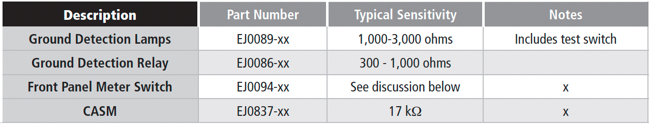
The Front Panel Voltmeter Switch option doesn’t have a sensitivity rating as such. It simply indicates a dc voltage that’s a function of the ground leakage resistance. It isn’t very useful below about 50 kΩ leakage resistance, but it has the advantage that it doesn’t use a bridge circuit, and so the battery has no ohmic connection to ground unless you are checking for grounds.
You can estimate the ground fault resistance using the meter switch option. Download the document JD0062-00 from this address: http://www.atseries.net/PDFs/JD0062-00.pdf.
The graph in this Application Note will help you determine the fault resistance. It won’t be accurate, though, if you have leakage paths from both battery terminals to ground.
A ground fault indicator light has one redeeming feature: you can see from across the room that you have a ground fault. As you can see from the table, though, it would be a serious fault.
Ground detection relays, because of their high inherent hysteresis, require a reset switch to clear the alarm once you’ve fixed the ground fault. It’s the only legacy alarm that is self-latching.
What’s the risk if there are faults from both battery terminals to ground? You called that a double fault.
6.3.4.5
If the resistance paths are nearly equal, they can’t be detected using a bridge circuit. And, if the resistance is low (a few hundred ohms or less), the fault can dissipate a lot of power, with resulting risk of damage or even fire. This condition is probably caused by electrolyte leakage; routine battery inspection should discover it.
What happens to the sensitivity if I have two chargers in parallel?
6.3.4.6
Another good question. If you have a CASM, or another option that uses a bridge configuration, the sensitivity is reduced. You could disable the ground fault detector in one of the chargers to restore the original sensitivity.
I’m paranoid. Can I have two ground fault detectors in my charger?
6.3.4.7
Some users do that. A popular combination is the Front Panel Voltmeter Switch, coupled with a CASM. Remember this, though: At the factory, that combination is wired so that when the voltmeter switch is used to check for grounds, the CASM ground detector is temporarily disabled. If the meter switch option is field-installed, that may not be the case.
One last question. You said that bridge detectors use high-value resistors. How high?
6.3.4.8
In the CASM, they’re 100 kΩ. In the AT charger, they’re 22 kΩ. Why the difference? Two reasons. The CASM is designed to work with 250 Vdc buses; the AT only goes to a 125 V bus. Also, AT series’ resistor values are smaller to get a wider sensitivity range.
CHARGER FAILURE
6.3.5
Ready for a little controversy? For years, charger failure alarms were simply zero-output-current alarms. And they weren’t really zero current but could give an alarm whenever the output current decreased below about 2% of the charger rating. This could be a frequent occurrence, or even a permanent condition, depending on the installation. Having zero output current doesn’t necessarily mean the charger has failed.
The NEMA PE 5 standard differentiates between charger failure and zero current alarms and gives several helpful examples of failure causes. But the requirement for an alarm boils down to this question: Regardless of the present output current or voltage, can the charger charge the battery when it’s called upon to do so?
The CASM has an advanced “True Charger Failure” circuit that tests the charger at intervals to be sure that it’s working and is connected to the battery. At each test interval, the circuit checks the charger output current. If it’s less than 2%, the circuit increases the output voltage slightly, and then looks for an increase in output current. If an increase is detected, the alarm circuit is satisfied that the charger hasn’t failed and goes back to sleep for eight more minutes. Of course, the output voltage is also returned to the proper setting. To understand why we do this requires a little background on the problems with a zero-current alarm:
-
If a charger has an automatic equalize option, such as an auto-equalize timer, the output current goes to zero when the charger switches from equalize back to float mode. This is because the output voltage setting suddenly decreases, but the battery voltage has been raised during equalize, and takes several seconds, or even minutes, to return to float voltage. A zero-current alarm gives an alarm, but the charger hasn’t really failed.
- In a site with parallel chargers, using random (not forced) load sharing, one charger may be set to a slightly higher float voltage than the other. It only takes a few tens of millivolts for that charger to “hog” all the output current. The idle charger would send a zero-current alarm, even though it hasn’t failed.
- Consider a site with a large battery (e.g., 400 Ah) and large charger (e.g., 100 A), but a very small standing load. The float current for that battery is less than 0.5 Adc. You would get a zero-current alarm.
The True Charger Failure mode in the CASM avoids these problems, and alarms only if the charger is really incapable of providing dc output current. If you still want a zero-current alarm, you can set up the CASM to act that way. But you must choose. You can’t have it both ways.
The AT charger takes a slightly different approach. The AT control circuit monitors the bus voltage and the charger output current, and if the bus voltage decreases below the set point (e.g., float voltage), it knows that the charger should be delivering its current limit value (or darn close) to the battery. If it isn’t, the control circuit calls that a DC Output Failure, and sends an alarm.
COMMON ALARM
6.3.6
The Common Alarm relay, also called a Summary Alarm, is a single relay that includes, or summarizes, all the standard alarms: High and Low AC Voltage, High and Low DC Voltage, Ground Fault, and Charger Failure. Using this alarm relay, you can monitor all the alarm conditions with a single annunciator, or a single port in a SCADA system. What you lose, obviously, is the ability to distinguish among the individual alarms; someone must visit the charger (it’s lonely, anyway) to determine what event caused the alarm.
In both the CASM and AT chargers, the common alarm has a 30 second delay. You can’t choose which alarms to include; they’re all in there, except that in the CASM you can remove the Charger Failure Alarm from the Common Alarm.
But I want to monitor the Charger Failure separately and group just the Ground Fault alarms. I don’t want the other alarms in there.
6.3.6.1
No problem. Just use the Theriault connection, described in Appendix C.
TO LATCH OR NOT TO LATCH – DO YOU HAVE A QUESTION?
6.3.7
Just one more. Maybe. In the section on ground fault detection, you mention latching. Do all these alarm relays latch?
6.3.7.1
No, but...
CASM relays don’t latch, but there’s an app for that, too. The EJ1193-xx option gives the CASM alarms the ability to latch, but it uses an auxiliary relay for each alarm. It’s a bit of a wirer’s nightmare.
Better to choose an AT charger with the optional auxiliary relay board. Starting in 2010, the relays on the auxiliary board could be set to latch, with no external wiring required. Just remember that a latching relay requires manual clearing (unless you have the communications option described in SECTION 6.5).