Starting DC Motors: Handling Sudden Load Demands
Part of Chapter Different Charger Applications
A FREQUENT REQUIREMENT at a site is to start a dc motor, a lubrication pump, or whatever. When a motor is first started, its inrush current must be supplied by the dc bus. If the inrush current exceeds the charger rating (which is usually the case), then the battery must make up the difference. The sudden demand depresses the battery voltage slightly, ensuring that the charger enters current limit (for more on this behavior, see Current Limit Alarm in SECTION 6.6.9).
The SCR/SCRF chargers and the AT chargers respond differently to these sudden load demands. The current limit control on the AT is fast, usually acting within one cycle of a 60 Hz ac line. The SCR/SCRF current limit control doesn’t take full effect for about 100 msec, or about six cycles.

The SCR/SCRF charger is normally supplied with a fast-acting fuse in the dc output circuit. When the dc motor is first connected across the dc bus, it looks almost like a short circuit. The delay in the current limit circuit can allow enough charger output current to flow (to the motor) to clear the fuse. To ensure reliable starting of dc motors with the SCR/SCRF charger, we recommend that you install the optional motor starting kit, which consists of a freewheeling diode to be wired across the output of the charger (but inside the dc output circuit breaker), and an upgrade to a slightly slower fuse.
With a slower fuse, is the charger still adequately protected?
Surely. If the purpose of the fuse were to protect the dc bus from excessive charger output current, the motor-starting fuse would be up to the task, since it has the same rating as the standard dc fuse. Actually, the more important role of the dc fuse is to protect the dc bus from an internal fault in the charger. The motor-starting fuse will also do that.
The AT10.1, AT30, and ATevo chargers are all designed to withstand dc motor starting requirements with no modifications. More is said about motor starting in SECTION 4.4.1.
The following are two case studies to help illuminate what happens in dc motor starting. In the first, a customer kindly provided oscillographic test data for starting a large pump motor; their data covered the first 100 ms or so of motor starting. We were asked to analyze the data to find the fuse rating that would withstand the motor inrush current.
CASE STUDY 1:
7.2.1

In Figure 7a, the horizontal axis ranges from 0.0 to 1.1 seconds. The vertical axis shows dc volts.
Based on the motor inrush and charger output current data provided by the user, we developed a simple equivalent circuit for the battery-charger-motor installation and built an incremental model. We used the model to analyze the behavior of the circuit to estimate the wiring resistances, and predict the behavior of the battery charger, assuming that the dc fuse wouldn’t blow.
Assumptions:
- The battery voltage decreases to the open-circuit voltage as soon as the motor load is applied.
- The battery open-circuit voltage is 123 V.
- The battery charger's bridge-output voltage is 132 V, and doesn't change for the first 80 msec after the load is applied.
- At 80 msec, the motor current is 640 A. The charger supplies 280 A of this and the battery supplies the remaining 360 A. This comes from the user’s data.
- The battery internal impedance is 0.015 Ω.
- Reverse current cannot flow through the charger. Also, after 200 msec, the charger output is limited to 83 A. This has been modeled as a geometric decrease in current, converging to 83 A.
- V(m), the motor’s back EMF, is described by V(m)= B × t, where B is empirically derived. V(m) becomes constant at 0.6 seconds.
- The motor armature resistance is 0.1 Ω, based on 5% per unit impedance at 60 A full load.
- The armature self-inductance is 6 mH.
- The battery charger’s dc circuit inductance is 4 mH, but the model works better if we assume an average inductance of 3 mH, since the inductance decreases at high currents.
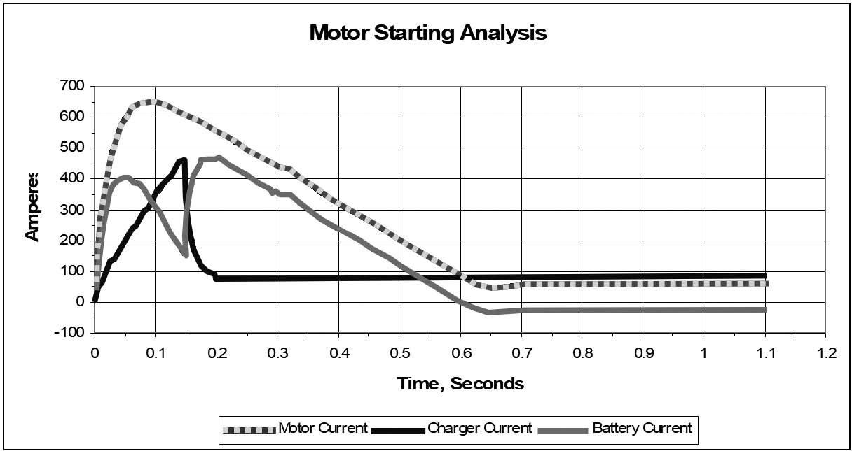
With these assumptions, the circuit was analyzed incrementally, resulting in the waveforms in Figure 7a. This graph is hypothetical; it predicts the behavior of the charger current and the battery current if the charger dc fuse doesn't blow.
This model conforms closely to the actual behavior of the motor inrush current and the charger current during the first 80 milliseconds. The rest of the behavior is extrapolated to conform to the actual measured motor inrush current.
There is an unknown factor in the model: I assumed that the charger dc inductors would not saturate during this period. If they would saturate, this might change the portion of the inrush current provided by the charger.
Based on the predicted peak charger output current of 400 A, using a type JJN-125 fuse* for F1 in the charger will allow the motor to start without blowing the fuse.
The second case study is a field report of an erroneous charger failure alarm, due to the action of the current crowbar circuit during motor starting. The current crowbar is a safety feature to protect the charger against a sudden fault on the dc bus. When the current crowbar is activated, the charger is forced to return to soft start. Remember that starting a motor can look almost like a short circuit until the motor gets going.
CASE STUDY 2:
7.2.2
The user’s original problem report for an AT charger rated at 24 V, 100 Adc was similar to the following:
Right now we are working on a problem with the fault signal from the charger. We have the charger connected to two 12 V, 100 Ah...batteries in series, going to a 24 V, 22 amp dc lube oil pump. When we first turn on our pump we get a low dc voltage alarm then a dc output failure.
After a minute, the output current [and] voltage stabilize and the faults go away. The output current from the charger starts out low, about 1 amp, and within a minute it stabilizes at 23 amps.
The slightly abridged analysis was (…the envelope, please…):
The user is trying to start a dc motor rated at 22 A. The inrush will be at least 220 A. That's typical: The inrush range varies from eight times to over 20 times the full load current, depending on the motor design.
The charger, of course, is limited to 110 A. The response time of the current limit circuit is fast, though not instantaneous. However, the response of the current crowbar is instantaneous. When the motor is started, the current demand is going to be shared by the battery and charger. The battery, surprisingly, can't deliver the necessary current instantaneously, and so the terminal voltage drops, possibly to less than 2.0 VPC (volts per cell).
This leaves the charger to try to make up the difference. The instantaneous current demand may activate the current crowbar, which sends the control circuit back to the beginning of a soft start. Thus, the dc bus voltage collapses by several volts, and will be determined by the characteristics of the battery alone for at least the next four seconds.
By that time, of course, the motor is up to speed, and the bus voltage has recovered to 2.0 VPC or higher. The battery is supplying the motor current, and the charger gives a dc output failure alarm because its voltage is below float, and its output current is below current limit – exactly the way we designed it. Once the charger output recovers to the float voltage, it begins to supply the motor current, and the alarms are reset.
I think, however, that the common alarm relay shouldn't transfer for 30 seconds, which should at least prevent any remote annunciator from being activated.
There are guidelines for calculating charger ratings based on load demands, battery size, recharge time, etc. Sales can help you with these. Unfortunately, these guidelines are inadequate when transient loads such as dc motors are thrown into the mix. You would think that rating the charger at five times the motor rating would be sufficient; in fact, it would be if it were an SCR charger. The issue here is "false" alarms (meaning a transient alarm that the user doesn't want to see).
Finally, the way a dc system responds to a motor starting event depends to some extent on the way it's wired. If the motor is electrically closer to the charger than the battery, you are more likely to see the behavior that the user describes.
FUSE COORDINATION
7.2.3
In the SCR/SCRF case study, you saw that the result was the choice of a specific fuse. For the purposes of motor starting, fuses are chosen to allow the peak charger-output current prior to the initiation of current limit, but still offer short-circuit protection for the rectifier SCRs and diodes.