How Are Relay Contacts Specified?
Part of Chapter Charger Alarms and Other Options
SOME MANUFACTURERS SHOW alarm relay contacts in the non-alarm condition as their document standard for schematic and wiring diagrams. Therefore, the contact designations you see on schematic diagrams may not be the same as the “on the shelf” (non-energized) relay designations.
In many applications, alarm relays are normally energized, so that a loss of power to the alarm circuit causes an alarm as a “fail-safe.” This is an essential protocol, for example, in an alarm that is intended to signal a low dc bus voltage. If power to the alarm circuit were to fail, an alarm signal would bring someone running to investigate the problem, just as if the dc bus voltage were too low. Presumably, that person would then fix the problem in the alarm.
Not all alarm relays are normally energized, though. As an example, consider the CASM (Combined Alarm & Status Monitor) alarm PC Board (in the SCR/SCRF charger). Part of the schematic diagram is reproduced in Figure 6a, showing the alarm relay terminal block and the labeling for the user’s external wiring.
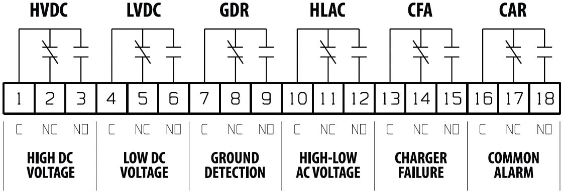
The markings for the terminal block clearly show the arrangement of relay contacts – in the order C (common), NC (normally closed), and NO (normally open) – for every relay in the option. The designations NC and NO refer to the non-alarm state of each relay. For the Low DC Voltage alarm, for instance, the terminals C and NO mark the contact that is open as long as the dc bus voltage is normal. If the bus voltage falls below the alarm point, the NO contact closes, and the NC contact opens.
The Low DC Voltage alarm relay is normally energized, so you know that the NC and NO contacts shown here don’t correspond to the labeling on the relay itself. By contrast, the High DC Voltage alarm relay isn’t normally energized because you can’t have a high dc voltage without ac power present, so we wouldn’t want an ac power failure to cause an erroneous High DC Voltage alarm. In this case, the terminal block is labeled with NC and NO as they appear on the non-energized relay.
The labeling on the terminal block in each case eliminates any ambiguity about how to wire to your alarm. The person installing the wiring doesn’t need to know anything about the relay or its state of energization, or about how the alarm circuit works.