A collection of Frequently Asked Questions regarding industrial battery chargers, batteries, and DC systems.
The most common requests for information from our customers are for ground detection options. Often when a ground detection alarm activates, the user believes the fault is the alarm setting or limited to the inside of the battery charger. For your convenience if an alarm is activated, the problem is best determined by measuring the voltage difference between the battery (-) to chassis ground and the battery (+) to chassis ground. The measurements should be the same if no other ground detection has been added to the dc bus. This will often determine severity of the fault.
The best way to troubleshoot the location is to disconnect sections of the dc system and continue to measure as above. Switching power supply loads have large capacitors connected from the dc input and chassis ground, and may have enough leakage current to cause ground faults. Another common problem is that the user has a grounded load and the Ground Detection Option is activated all the time. This may become undesirable. Most Ground Detection Options can be disabled by reading the user's manual. Battery chargers that charge only a portion of a bank cannot use ground detection. This is a rare occurrence, and most often comes in the form of two (2) 130 Vdc battery chargers being used to charge a 260 Vdc bank.
For your convenience, we have codified a handy trouble-shooting guide called Ground Detection In The Real World (JD5032-00). Hopefully, this will be a great resource our users of our battery charger products in lieu of an actual technical service call.
It is important to properly size the charger to the application and to perform said sizing using industry accepted techniques. This consideration will ensure that the charger when applied is properly sized and neither oversized nor undersized.
(AH removed x 1.R)/(T (desired recharge time))+L (constant loads) =Amperes Charger
For more details of how to properly size your utility battery charger please reference JF5045-00.
In order to best serve you, our ultimate customer, the user of HindlePower products, we have arranged access to our products through industry leading battery manufacturers and specialized resellers. By contacting our sales department at HindlePower we will refer you to a locally qualified reseller and/or a National/Internationally represented reseller with offices local to you. In either case we will be with you for the entire process from “Before, During and After the Sale” to help ensure your complete satisfaction.
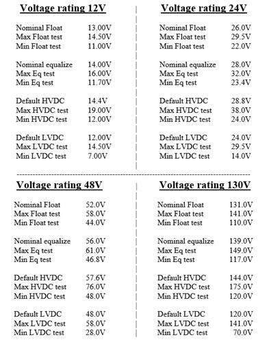
Common customer calls come in concerning the proper Float and Equalize settings on the charger for their specific battery. Each type of battery has different float and equalize settings. Consult your battery manufacturer's documentation for specific values and settings for your battery type.
Electronic equipment that contains switching elements can generate harmonic distortion that is reflected back onto the ac supply lines in a building or facility. This is true, for example, of computer power supplies, and also of SCR phase-controlled battery chargers. Harmonic distortion refers to currents and voltages flowing in the ac wiring that are multiples of the normal line frequency (50 or 60 Hz) - for example, 120 Hz (second harmonic, 2 x 60 Hz) or 180 Hz (third harmonic, 3 x 60 Hz). Like freeloading relatives, these harmonic currents don't do any work, but they can cause extra stress.
When the switching components in these types of equipment turn on and off, ac current harmonics are generated within the equipment. The current harmonics are translated into voltage harmonics by the impedance of the ac wiring connecting the equipment to the ac supply. The higher the impedance of the supply wiring, the higher the voltage harmonic distortion will be. The voltage harmonic distortion can be a problem if it creates extra heating in transformers and in the power supplies of other connected equipment.
Most equipment that operates on the ac supply can tolerate up to 5% voltage THD (total harmonic distortion) without difficulty. In most industrial installations, the supply wiring has a low enough impedance so that the voltage THD generated by a battery charger doesn't approach the 5% value. This is true even for the 3-pulse SCR/SCRF product.
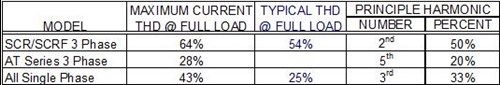
The table below presents the worst-case "textbook" values for current harmonic distortion for the types of rectifier circuits used in phase-controlled battery chargers. These numbers are for rectifiers operating at full resistive load, with no battery and no series inductor (L1). At other than full load, the harmonic content varies, in a predictable but complex manner. The table totals the harmonics through the 13th harmonic; higher harmonics are very small contributors. The last two columns show the lowest harmonic component, which is usually the major contributor to distortion. Remember that these harmonic currents usually result in less than 5% total voltage harmonic distortion.
The good news is that the presence of the charger main inductor (L1) reduces harmonic currents, and the harmonics are often lower than the textbook values. It's impossible to predict exactly what the harmonic content for any charger will be, because the exact load conditions and operating point are unknown. For this reason, we show the maximum theoretical numbers in the table. The 3-pulse design (SCR/SCRF) is the worst offender for input harmonic currents; if input harmonics are a sensitive issue, specify the AT30 series. Where available, the table also shows typical test results for a charger at full load.
The AT series battery charger can use an optional battery temperature probe for temperature compensation of the dc output voltage. The probe is designed to mount "on or near the battery." The instructions for installing this probe, in the AT Operating Manual, advise the user not to mount the probe on the battery itself.
Confused?
Apparently, so are many of our customers. In this note, we'll attempt to clear up the ambiguity.
When the AT series temperature probe was first designed, we were advised that the adhesive might not be compatible with some plastic materials, including some used in manufacturing battery jars. To avoid problems, we advised staying away from all plastics as a mounting surface. We recently researched the adhesive again, and can provide some additional guidance.
The mounting tape used for the temperature probe is a 1 mm (0.045") thick neoprene foam, coated on both sides with an acrylic adhesive. The adhesive is compatible with a wide range of materials, including many plastics. It also maintains strength at elevated temperatures (up to 100°C, although we hope your battery never gets that hot!). The neoprene foam conforms to irregular surfaces, allowing the probe to be mounted on rough or coarsely painted surfaces.
The adhesive is optimized for high surface energy materials (most metals, for example). Thus, bare wood and galvanized steel are still no-no's, although untreated zinc is all right. The adhesive is compatible with many polymers used in battery manufacturing. However, some polymers have very low surface energy, and reliable adhesion may be difficult to achieve. Those are the materials at the bottom of the list below. The materials near the top should provide good adhesion. Most painted surfaces are OK, but you need to know that the paint will stick to the surface like, well, paint.
We still recommend an intercell connector as the best place for mounting the probe. In a battery room with little air movement, the connector will be closer to the actual battery internal temperature than the outside of a battery jar.
Here is a list of compatible materials:
- Most metals (copper, stainless steel, lead-plated copper, etc.)
- Glass
- Nylon
- Polyester
- Epoxy paint
- Polyurethane paint
- ABS
- Polycarbonate
The following may have poorer adhesion characteristics, but are still compatible:
- PVC
- Acrylic
- Polystyrene
- Polyethylene
- Polypropylene
And of course, good luck with Teflon.®
In response to many questions on this topic; most folks are asking about how a battery charger can call itself a battery eliminator and yet not perform like a battery? This is a great question unfortunately the terminology "battery eliminator" is not as precise as it could be. Much like "duck sauce" is not made from ducks, "lobster sauce "has no lobster in it or as the late George Carlin would say; "Why do we park on a drive way and drive on a parkway?" certain phrases are not always completely precise but their meaning needs to be understood just the same.
For battery chargers we have a few assumptions, first the battery charger is there to charge the battery and operate the steady loads when the AC is on. If the charger were to operate the switchgear during an electrical outage it then becomes the same as a battery. Therefore, if it were a battery why call it a battery eliminator? We could just call the charger the battery too; confusing? Not really! We must all agree that a battery charger is a battery charger and a battery is a battery! (Sigmund Freud would like that.)
Although certain applications may find it practical to use the charger to operate switchgear this would not cause us to consider offering "switchgear operating curves" for our chargers. This effort would involve an added feature that we would neither be able to control nor predict performance. While it is true that in certain cases these unusual performances may occur, we would not provide that as part of our operating capability because there is no specific standard that determines how this works with consistency or repeatability.
The battery charger will operate as a power supply up to its current limit rating within the confines of both the slow start circuit used to protect the load and battery while operating within a step change rate that occurs within 200ms and 500ms. (See NEMA PE5, Section 5.10) We do not offer "switchgear use" curves to predict this because the battery capacitive reactance, resistances, load characteristics, and a host of other issues affect this performance.
Remember, in any battery/charger scenario the battery controls the bus voltage and the charger provides the current to maintain that voltage. What is sometimes requested of us is for the charger alone to operate switchgear, based on calculating a defined current performance with an unpredictable bus voltage in order to determine how much current I can get for how long? There is no equation to solve for this repeatedly or consistently because of the many variables involved.
Further issues exist when trying to operate an inductive device whose true current demands are not always readily available. Those solenoid devices used to operate switchgear can demand very large up front currents that the batteries will deliver but the charger cannot. These currents are not always clearly stated in the switchgear specifications and have been recorded to be as much as 10 times or more of the device's plate rating. The charger is limited to its current limit as the maximum output current available and initially when current limit is achieved the full voltage may not be available, further detracting from this as a viable and saleable possibility.
When exploring the issues of Constant Loads vs. Transient Loads the controls put onto a battery charger are very important features. If a utility type battery charger is not properly regulated it would go into overvoltage and or overcurrent either of which could harm a battery or load. Therefore, if the charger could accommodate the potential wild swings that a battery can perform then the charger could damage the battery because you need to include the fact that an increasing voltage is also possible from the charger.
The battery starts discharging at OCV (open circuit voltage) without any external energy source while the charger has the AC input to draw from. When a battery outputs, it outputs current, while the voltage trails off but a charger and or power supply that is not regulated would then output currents such that the voltage could exceed normal. The utility battery charger has what is known as a rectangular output making it uniquely qualified to use current to control voltage by means of regulation. The battery just outputs current while the voltage decays. These are two very different ways of operating.
Considering all the possible variables, we cannot provide a table to determine switchgear operation using only a battery charger. Said ability is fraught with downsides and will only cause problems in the long run. If a specifier believes that a certain charger will operate their switchgear then it must remain with the specifier to determine.
We have no way of testing, calculating, or determining all the possible variables that may or may not allow switchgear to operate off a battery charger without a battery connected. Unless the AC is on and the operating load falls within the confines of our advertised ability, where the desired current demand coupled with a slow start capability that includes step changes to occur within 200ms to 500ms up to but not exceeding our current limit level of 110% of rating, we cannot assure you that for this scenario switchgear will operate without a battery connected.
In the final analysis, the term battery eliminator just means that the charger may operate as a regulated power supply without the battery connected with the output ripple not exceeding the NEMA PE5 standards for amplitude.
-
Enclosures used for HindlePower industrial battery chargers meet NEMA Standard 250-1085, and are available for types 1, 4 and 12. An optional drip shield assembly is also available as an add-on to a standard NEMA-1 type enclosure, making the combined assembly compliant to NEMA-2 (*) type standards. To determine a general equivalency between NEMA types and the European IEC 529 "IP" enclosure standard, use the table below. Remember that there is no exact correlation between NEMA and the IEC IP system, and you must ensure that any enclosure for IEC standards meets the requirements outlined in the second "The IEC IP System" table below.
-
NEMA-1 type enclosures meet or exceed IEC IP23
-
NEMA-12 type enclosures meet or exceed IEC IP32
IEC 529 NEMA 250
TypeGeneral Description Of Enclosure
IP00 1 vented top IP20 1 vented top IP21 2* vented top with drip shield IP22 12 solid top, gasketed door, side vents IP30 1 vented top with bug screening IP31, IP32 12 solid top, gasketed door, side vents IP33 4 solid top, gasketed door, side vents IP41, IP42 12 solid top, gasketed door, side vents IP43, IP44 4 solid top, gasketed door, side vents IP5x 4 solid top, gasketed door, side vents The IEC IP System
The degree of protection afforded by an enclosure is designated by a four-character code, "IP" followed by a two-digit number. The meanings of the numbers are defined below. For example, IP21 protects against the ingress of moderately sized solid objects (approximately ½in / 12.5mm) and dripping water.Numeral First Number Second Number 0 not protected not protected 1 protects against solids objects
of 50mm / 1.97in dia. and largerprotected against vertically
falling water drops2 as above, but objects 12.5mm /
0.49in diameter or greateras above, but with enclosure
at 15° angles3 as above, but objects 2.5mm /
0.10in diameter or greaterprotected against
spraying water4 as above, but objects 1.0mm /
0.04in diameter or greaterprotected against
splashing water5 protected against dust: ingress not
prevented, but shall not penetrate
in a quantity to interfere with
satisfactory operation or safetyprotected against
water jets6 dust-tight, no ingress of dust protected against
powerful water jets7 - n/a - protected against temporary
immersion in water8 - n/a - protected against continuous
immersion in water -
Please refer to this document: AC DC Interrupting Capacity
A standard battery charger/rectifier may be operated at any ambient temperatures up to -1°F to 122°F (-18°C to 50°C) w/o derating. For more information on this, click the link below.

Technical Support
HindlePower offers an array of technical support tools to assist you with all aspects of your battery charger. We have the technical expertise to provide even the novice electrician troubleshooting help over the phone. Monday– Friday, 8:00am-5:00pm EST, our technical staff is available to give you step-by-step guidance and help repair your battery charger in the unlikely event of a failure. 610-330-9000

How to Videos
Our short but informative YouTube videos offer easy, step-by-step instructions on the most common installation, operation and trouble-shooting procedures.